PLEASE ROTATE ME

Telink Staff
September 13, 2022
Applications
Telink’s Wiki website provides software SDKs of various application scenarios for customers to use. This series of articles focuses on the “Bluetooth® Low Energy (LE) Single Connection,” an SDK for single-connection applications where a Bluetooth chip makes a point-to-point connection with another Bluetooth LE device, either as a master or as a slave.
This article describes the uses of this SDK’s B85m_master_kma_dongle routine in detail to help customers familiarize themselves with it quickly and speed up the development of projects.
B85m_master_kma_dongle in the single-connection SDK is compatible with 825x chips and 827x chips, so the compilation options are divided into 825x_master_kma_dongle and 827x_master_kma_dongle (which, moving forward, will collectively be referred to as master_dongle).
The master_dongle routine is the only master-host demo routine in the single-connect SDK. Kma is the abbreviation for keyboard mouse audio and is used based on the dongle board, hence the name. As a host, it can connect and communicate with slave routines such as bl_sample, bl_remote, and module. The main functions of this routine include BLE data transmission, OTA upgrade, and more.
*Note 1: By default, the master_dongle routine has no low-power consumption functionality. Users can implement it by following the instructions in the handbook’s low-power section or using the host routines with low power in the multi connection SDK.
*Note 2: Due to the RAM limitations of the Bluetooth chip, the master cannot provide full-service discovery functions. Currently, only simple SDP services are available in the routine (EX: service discovery based on the specific UUID provided).
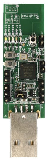
As an example, let’s look at the TLSR8258 master dongle routine, which is based on the TLSR8258 dongle board (model number C1T139A3_V2.0A), as shown below:
The previous article, “b85m_ble_remote routine,” mentioned the use of the remote and master dongle to transmit BLE audio. This article will further discuss it in detail.
The OTA upgrade here refers to the OTA upgrade performed by the master dongle as the master to the slave. The ble_sample, ble_remote, and module routines in the single-connection SDK are all slave demos that support the OTA function. This article will use the ble_sample routine to describe the OTA upgrade method. Prepare two TLSR8258 dongle boards. The one for the device upgrade is called DUT, and the other for the OTA upgrade is called the master dongle.
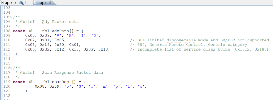
1. To identify whether the OTA upgrade was successful on the DUT, modify the broadcast name and scan the reply data of the ble_sample routine. Use the mobile phone to scan the broadcast name before and after the upgrade to verify the OTA upgrade. For example, the files generated after compilation are named as follows:
8258_ble_sample_VHID.bin
8258_ble_sample_XHID.bin
Download the 8258_ble_sample_VHID.bin firmware to the DUT, then use the mobile phone to scan the broadcast. You should then see the Bluetooth device with the VHID name.
2. Use the BDT tool to download three firmware to the master dongle board, as shown in the following figure:
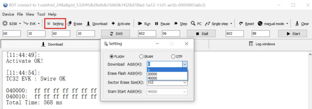
Note: The master_kma_dongle.bin firmware is the main program and can be upgraded according to different keys. The reason for downloading two OTA firmware is that users can quickly test the OTA upgrade back and forth between 8258_ble_sample_VHID.bin and 8258_ble_sample_XHID.
3. Both DUT and master_dongle are powered on. The master_dongle board is powered on by default. None of the 4 LEDs should be on. The operations on the master dongle board are as follows:
Initial state:
Once the pairing is successful:
OTA state:
4. After the OTA upgrade is successful, scan the broadcast with your mobile phone to see the broadcast of the XHID name.
*Note 1: After the OTA upgrade is successful, the mater_dongle will automatically reconnect to the DUT. It is recommended to power off the master_dongle board. You can then use the mobile app to scan and view the upgraded results according to the broadcast name.
*Note 2: You can also use the mobile app to perform an OTA upgrade on the slave. Telink provides iOS- and Android-based app demos and source code for OTA upgrade demonstrations. Customers can then use these demonstrations to develop their own mobile apps.