PLEASE ROTATE ME

Telink Staff
September 1, 2022
Applications

Telink’s Wiki website provides software SDKs of various application scenarios for customers to use. This series of articles focuses on the “Bluetooth® Low Energy (LE) Single Connection,” an SDK for single-connection applications where a Bluetooth chip makes a point-to-point connection with another Bluetooth LE device, either as a master or as a slave.
This article describes the uses of this SDK’s B85m_ble_remote routine in detail to help customers familiarize themselves with it quickly and speed up the development of projects.
B85m_ble_remote in the single-connection SDK is compatible with 825x chips and 827x chips, so the compilation options are divided into 825x_ble_remote and 827x_ble_remote (which, moving forward, will collectively be referred to as ble_remote).
The ble_remote routine is a more complex slave routine and is the source routine of the Bluetooth voice remote control.
Telink has a variety of voice remote control solutions, which you can find at this link:
http://wiki.telink-semi.cn/wiki/solution/RCU/
Main functions of this routine: Bluetooth connection and enumeration as HID devices, matrix key scanning, voice acquisition, BLE transmission, IR function, battery power detection, low power consumption, OTA upgrade, etc.
You can download related resources (software SDK, hardware reference design, etc.) for remote controllers based on TLSR825x and TLSR827x chips from the following link:
http://wiki.telink-semi.cn/wiki/solution/RCU/Generic-Bluetooth-LE-RCU/
The audio remote control Audio RCU based on TLSR825x and TLSR827x is shown in the following figure:
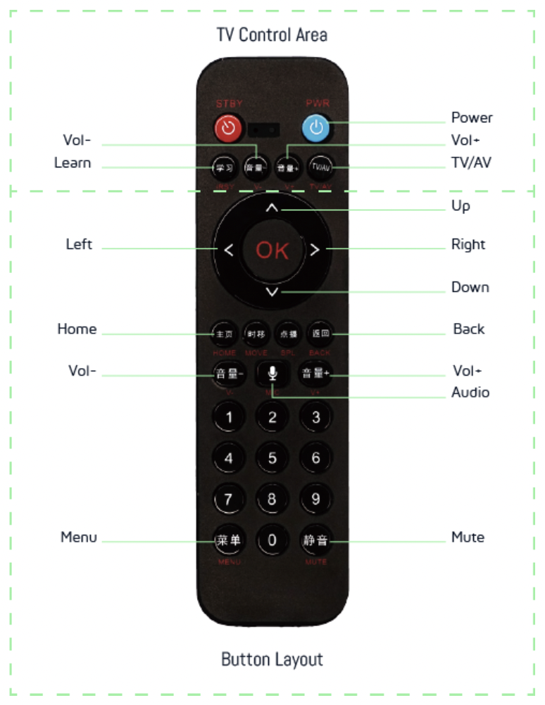
There are two ways to use Audio RCU. One is to directly connect to the smart TV via Bluetooth to control the TV. The other is to use it with the kma master dongle (as will be demonstrated in the kma master dongle article later). The following describes the first method of use, replacing the smart TV with a mobile phone.
Note 1: The ble_remote routine is an HID device and does not need to be used in the mobile app. If you use the mobile app to connect, you will not see the effect of the above buttons.
Note 2: Some keys on the RCU may not be supported by the mobile phone. Because RCU is a Bluetooth voice remote control, it can be used as a remote control and connect to smart TVs, set-top boxes, and other devices via Bluetooth. Some keystrokes are interpreted differently on mobile phones and smart TVs.
In the ble_remote app_config.h file, you will find macro definition switches for the main functions.
The low-power function is enabled by default, and the macro is defined as:
#define BLE_REMOTE_PM_ENABLE 1
#definePM_DEEPSLEEP_RETENTION_ENABLE 1
In addition, the power consumption is optimized for when the remote control is idle. If the broadcast exceeds 60s, it will automatically enter deep sleep (deepsleep mode) and stop the broadcast. If a connection is established but there is no keystroke within 60s, it will disconnect and enter deepsleep mode. The code in blt_pm_proc() is shown in the figure below.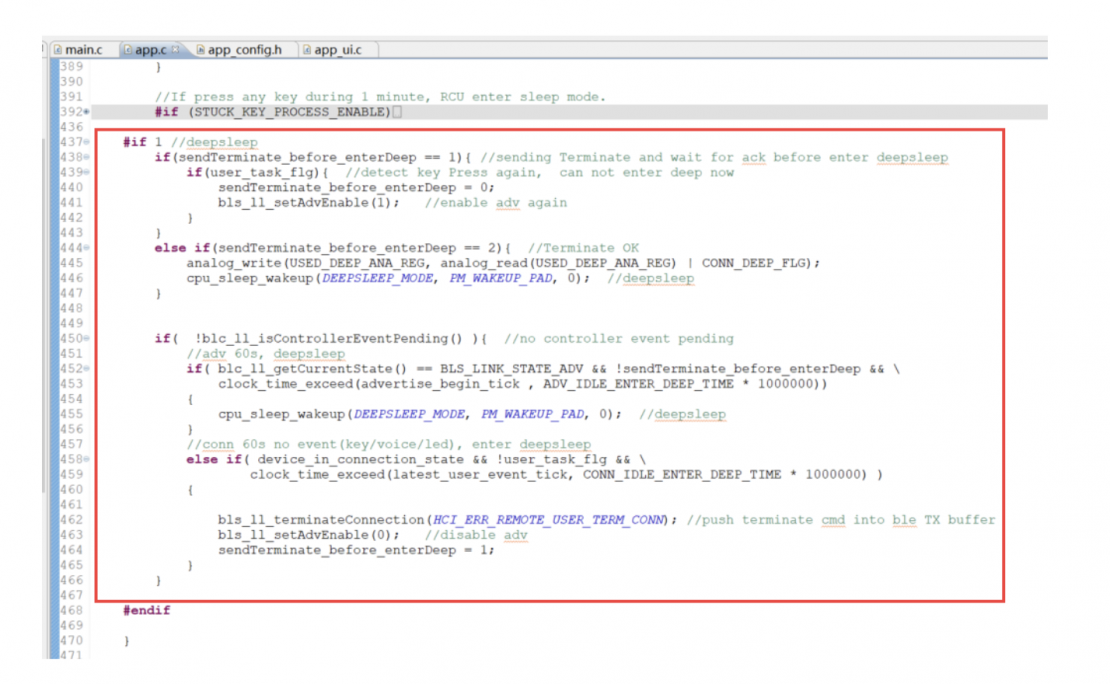
Note: When Bluetooth is connected, you must first disconnect and receive the ack before entering the low-power mode.
The remote control has many buttons, and Telink provides the code for determinant scanning keys. This section is based on the “Key Scan” section of the routine code.
Voice capture supports 16K and 32K sampling rates, and voice transmission uses BLE to transmit compressed voice. For implementation principles and mechanisms, please refer to the “Audio” chapter of the handbook. The macro definition switch is:
#define BLE_AUDIO_ENABLE 1
In addition, the routine supports a variety of compression formats for voice streams, which can be selected using macro definitions:
#define TL_AUDIO_MODE TL_AUDIO_RCU_ADPCM_GATT_TLEINK
Using ADC to collect battery power is a common application scenario. This routine provides code implementation, principles, and instructions for use. Please refer to the “Low Power Detection” section of the handbook.
The macro definition switch is:
#define BATT_CHECK_ENABLE 1
This routine also supports infrared remote control. Please refer to the “IR” chapter of the handbook for the implementation principle and mechanism. Infrared remote control is not enabled by default.
The macro definition switch is:
#define REMOTE_IR_ENABLE 0
OTA upgrade is supported by default. Please refer to the “OTA” chapter of the handbook for the implementation principle and mechanism.
The macro definition switch is:
#define BLE_REMOTE_OTA_ENABLE 1
There are two types of firmware checks. One type uses CRC32 checks at the end of the firmware to verify that the firmware is complete. Read the firmware from the flash at initialization to calculate CRC32 and compare the values. If inconsistent, the firmware is considered damaged. For more information, please refer to the description in the “14.4 Firmware Integrity Self-Check” chapter of the handbook.
The macro definition switch is:
#define FIRMWARE_CHECK_ENABLE 0
The other type uses a UID-based firmware check, which is implemented on the production line by capturing a 16-byte UID in plaintext from the chip, encrypting the UID (ciphertext), and burning it to a fixed address on the flash. In the program code, the chip UID is also encrypted again by the same menthod during initialization. It is then compared with the ciphertext burned in the flash. If the values are consistent, it is considered OK to continue running. If inconsistent, it will stop running. For details, please refer to the description in the “14.3 Firmware Digital Signature” chapter of the handbook.
The macro definition switch is:
#define FIRMWARES_SIGNATURE_ENABLE 0
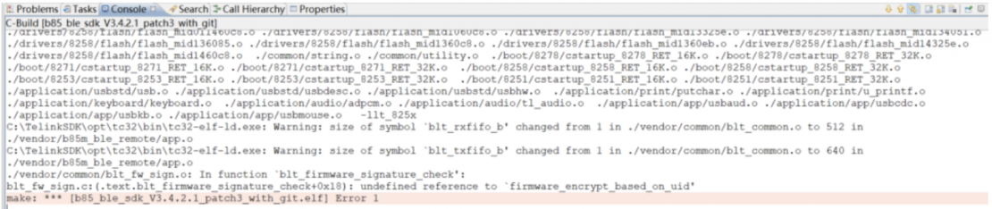
Note: After opening the FIRMWARES_SIGNATURE_ENABLE macro definition, the compilation will report an error, indicating that firmware_encrypt_based_on_uid is not defined, as shown in the following figure:
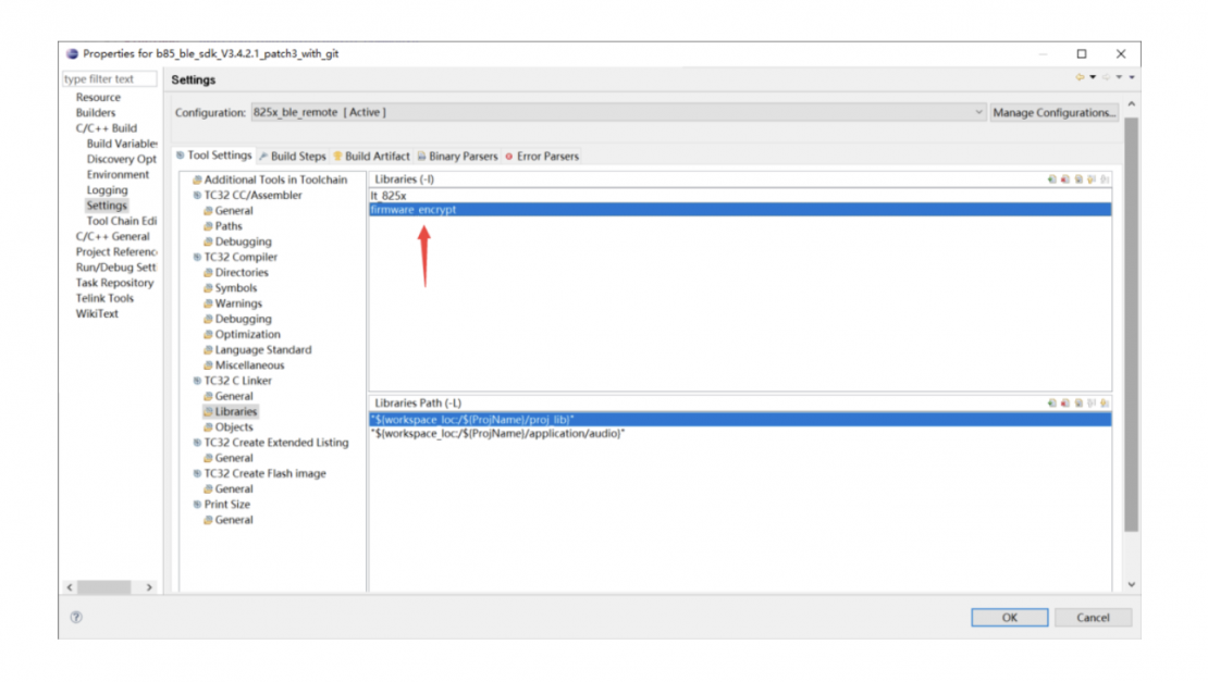
Solution: There is a “libfirmware_encrypt.a” library file in the proj_lib folder, but the project does not contain the library file. The specific operations are as follows: Click on the project –> Properties –> C/C++ Build –> Setting –> Tool Settings Library page, click on “+”, type “firmware_encrypt” in the window, and click OK.
Note: Check for mistakes in the name of the added library file. The name of the library file “libfirmware_encrypt.a” needs to be removed from the beginning and end (i.e., remove lib and .a).
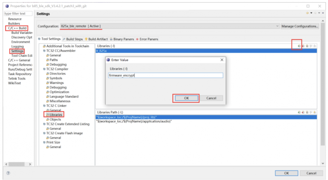
The added effect is shown in the following figure. After cleaning and rebuilding, the compilation should pass.